UAVCAN is an open communication protocol for real-time intravehicular distributed computing and communication based on modern networking standards. UAVCAN may have its origins from CAN Bus, but interestingly stands for Uncomplicated Application-level Vehicular Computing And Networking, not connected to CAN. BatMon is a modular, lightweight Battery Management System capable of communicating on different low level communication protocols such as I2C, CAN and LIN bus.
Every time we explore a new concept or build a prototype, we find that using the Arduino ecosystem speeds up the build of a version 0.0 mock up. We have often gone as far as to utilize the ecosystem for many of its libraries in production systems.
Brief overview of UAVCAN protocol
UAVCAN, and specifically the v1 version, is a fairly new protocol for both hardware vendors and hobbyist-tinkerers. We thought it’d be a great first step to demonstrate a UAVCAN v1 protocol using Arduino, an MCP2515 and BatMon. We are utilizing UAVCAN Drone DSDL (DS-015) for publishing Battery Monitoring System (BMS) messages to Arduino. It is helpful to walk through an overview of UAVCAN v1 protocol to understand that this means.
UAVCAN is a peer-to-peer protocol without a “master” where all nodes are equal. It enables multiple sensors/nodes to exist in a single network minimizing the amount of physical wires required to interconnect all of these systems. A high speed data network, such as one below for a drone system, is possible with a three wire network (Ground, CAN_H, CAN_L).
The important feature (this is really enabled by the CAN bus which is one of the supported transport layers) exploited by UAVCAN is arbitration of the bus to transmit higher priority packets while lower ones are paused for a specified duration. For example, the above network would prioritize the ESC critical-error packets above the BMS’ warning packets.
UAVCAN is designed as a general/flexible protocol with robust interoperability, which has the downside that designing a simple task for communicating data between two nodes has a very steep setup overhead. We have set up a “hello world” example to smoothen this.
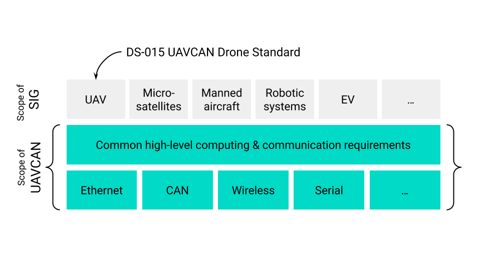
UAVCAN requires the existence of an application level DSDL (a commonly spoken message format) to be shared between the nodes that communicate with each other. In the figure below, specific Special Interest Groups (SIG) are responsible for building their standard DSDL that can be widely used in the SIG’s ecosystem. DS-015 is one such example built by the UAV community.
This DSDL is used by a transpiler to build programming language specific header files that are used to build the firmware for the different nodes as shown below. The DSDL is the only piece of data shared between the nodes.
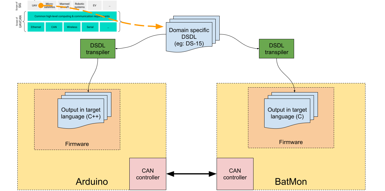
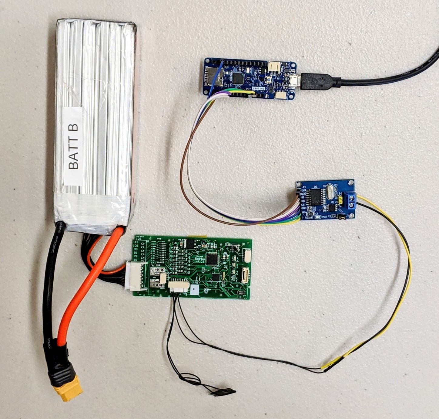
We publish a few messages that are relevant to BMS from BatMon; an Arduino MKR Zero will subscribe to those messages and display them in the serial console. Note that the CAN controller is not part of Arduino (like is shown in the above picture), but is available as a separate module.
Port-ID and Node-ID Assignment
This section is a bit too in-the-weeds, but it’s worth understanding for the curious ones. We need to understand the brief overview of the workings on the CAN Bus first.
Let’s take the CAN bus in a drone example. The smallest granular information that can be transmitted in a CAN bus is a frame. All nodes connected to the bus can transmit and receive frames. CAN protocol uses a clever technique to prevent multiple nodes from transmitting at the same time, and important frames to take control of the bus (Read more)
This system requires that (1) the type of each frame be known and (2) the sender of each frame be identified. UAVCAN v1 specifies the type of a frame using Port-ID and identifies the node, as you guessed it, using the Node-ID.
Historically, these IDs were assigned statically (could not be changed on the embedded devices). Though this system works for small ecosystems, UAVCAN v1 strictly requires that both these IDs be externally changeable. Note that the Arduino sketches used here have hardcoded the port and node ID. So you’ll have to change that if you decide to ship v1-conformant products.
Hardware Requirements
Software requirements and references
- 107-Arduino-MCP2515 library
- Rotoye fork of 107-Arduino-UAVCAN library. This will be merged to the main repository (https://github.com/107-systems/107-Arduino-UAVCAN) through this PR.
References
- The UAVCAN Guide: This page is quite long, but describes in detail the history, the future and the reasoning behind building the UAVCAN protocol
- UAVCAN DSDL repository: Contains definitions of the regulated UAVCAN v1 data types.
- UAVCAN v1 specs: Formal specifications for UAVCAN v1
- Smart battery interface from the UAVCAN Drone profile (a.k.a. DS-015): Data format to publish and subscribe to BMS data
- DS-015 UAVCAN Drone Standards: This is an application level definition that will be soon followed by the PX4 community.
- Nunavut: A command line interface to convert from DSDL files to a programming language header and source files.
Setup
Hardware Connections
The Arduino Zero is connected through its SPI interface to the MCP2515 board. The CAN High and CAN Low wires from the BatMon data connector are connected to the MCP2515 board.
Software Setup
Module directory and their functionality
There are two Arduino libraries which are required to run this example. One is 107-Arduino-MCP2515 which provides an interface to an MCP2515 chip that provides CAN communication. This library can be used to communicate with CAN devices. It has examples for listening for CAN messages on the bus. The other library is 107-Arduino-UAVCAN which uses the UAVCAN protocol to communicate. This provides several examples for sending different UAVCAN message types back and forth.
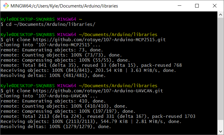
The Arduino libraries need to be downloaded into the Arduino libraries folder in the user Sketch folder. On Windows, this is commonly ~/Documents/Arduino/libraries. Once in that folder, the libraries can be downloaded using git. Use the command git clone https://github.com/107-systems/107-Arduino-MCP2515 to clone the MCP2515 library and git clonehttps://github.com/rotoye/107-Arduino-UAVCAN.git to clone the UAVCAN library. Now these libraries can be accessed from any sketch in the Arduino IDE using #include <ArduinoMCP2515> and #include <ArduinoUAVCAN>.
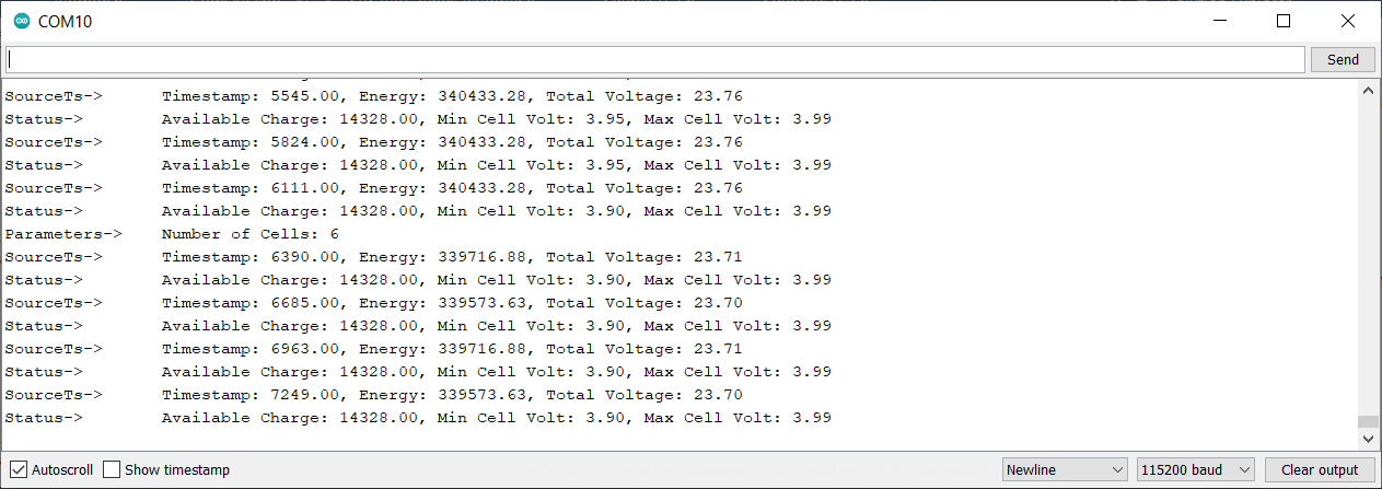
Data displayed on Arduino Console
The BatMon will send both SourceTs and Status messages to the Arduino. These can be read from the Arduino serial terminal.
Regenerating Data Type File from DSDL
This library source controlled the header files generated from the DSDL data type(UAVCAN specifically suggests against this, but it is added to make it easy for novice users to get started on UAVCAN). If the DSDL definitions are edited, the standard DSDL data type header files need to be re-generated and added to the 107-Arduino-UAVCAN library. These can be generated using Nunavut through the command line interface (CLI).
- Clone the UAVCAN public_regulated_data_types repository into any directory.
- Install the nnvg CLI.
- For GNU/Linux, install nnvg using Python pip
- python -m pip install nnvg
- nnvg –target-language c –target-endianness=little Path/to/Repo/public_regulated_data_types/reg –lookup-dir Path/to/Repo/public_regulated_data_types/uavcan
- nnvg –target-language c –target-endianness=little Path/to/Repol/public_regulated_data_types/uavcan
This should have created a folder called nunavut_out that contains three subfolders- nunavut, reg, uavcan. If using the Arduino IDE, move each of these folders into Arduino/libraries/107-Arduino-UAVCAN/src where Arduino is the user sketch directory. Note that the lack of -I flags in Arduino UI has resulted in manual editing of certain DSDL definitions.
EDIT: The readme of https://github.com/107-systems/107-Arduino-UAVCAN repo has updated instructions for generating header files from DSDL.